Sediment Delivery Systems
Introduction
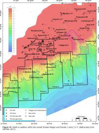 On the Scotian Shelf, within the central portion of the Sable Subbasin, reservoir quality sands are generally common within the Jurassic Mic Mac and Cretaceous Missisauga Formations. The Mic Mac Formation records this first phase of delta progradation into these subbasins, represented by distributary channel and delta front fluvial sands cyclically interfingering with prodelta and shelf marine shales. A series of thick sand-rich deltaic, strandplain, carbonate shoals and shallow marine shelf successions (Missisauga Formation) dominated sedimentation throughout the Early Cretaceous. These Mic Mac and Missisauga sands are the producing reservoirs of the five (Venture, South Venture, Thebaud, North Triumph and Alma) Sable Offshore Energy Project (SOEP) gas fields. Including the above five gas fields there are a total of 23 Significant Discoveries in the Sable Subbasin and a considerable number of wells with gas shows. Given the volume of sand present in the shelfal Sable delta complexes, it was anticipated that significant amounts of sand should have been deposited as turbidites basinward of the Sable Subbasin. Subsequent deep water drilling did encounter sands (Annapolis G-24: 42 m net sand, Crimson F-81: 20 m net sand, Newburn H-23: 40 m net sand and Tantallon M-41: 17 m net sand, see Figure 16 for well locations) and in some cases these sands were gas charged. However, the low net to gross in these wells relative to the high net to gross landward in the Sable Subbasin is perplexing, and has created questions regarding the shelf to slope transition in the central Scotian Margin. The following outlines the approach and results of a study undertaken by the CNSOPB to better understand the connection between shelf and slope deposits.
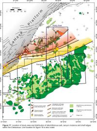 Shelf margin canyoning has been identified throughout the Cretaceous interval across most of the central Scotian Shelf. Canyon systems on the western portion of the Sable Subbasin (near the Alma wells) were previously identified in the NS08-2 call for bids package. Since this call package in 2008 seismic mapping across the shelf has progressed and a considerable number of new canyons have been identified. The full suite of mapped shelf margin canyons and paleographic shelf edge trajectories are shown in figure 17.
 Also noted in figure 17 is the outline of a study corridor that was chosen to link the canyons on the shelf to downdip equivalent age depositional thicks. This corridor was chosen because of the density of data, good imaging of fluvial systems, density of canyoning and the deepwater well control provided by the Annapolis and Crimson wells. The following describes the fluvial systems and canyon systems, within the study area, and provides an explanation for the well results at Annapolis and Crimson.
Sequence Correlation
 A composite seismic line drawing was developed to be used as a type section for sequence correlation within the central Sable Subbasin and to highlight the features indicative of the shelf to slope transition (Figure 18). To optimize the seismic imaging, the route avoids shallow salt structures and areas affected by extensive listric faulting caused by salt expulsion and basin subsidence while remaining within continuous 3D seismic coverage across the shelf and slope. This line is tied to multiple wells on the shelf and slope, however, in order to intersect all the features of interest (i.e. canyon erosion and expanded growth sections on the slope) this line does not directly intersect all key wells.
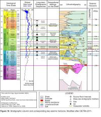
 The 160 km long profile begins at the Uniacke G-72 well on the shelf and extends onto the Scotian Slope ending near the 3500 m bathymetric contour (Figure 16). Figure 19 is a stratigraphic column which links the key seismic horizons noted on the line drawing to the lithostratigraphy of the Scotian Margin.
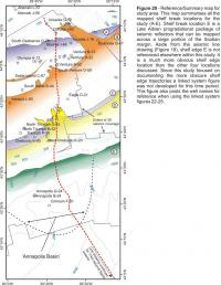
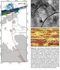
 The location of features interpreted to be shelf edges are noted on the line drawing by the circled letters A-E and a map view of their basinward progression is shown on figure 20. A description of the features used to delineate the shelf break trajectories is discussed below.
Shelf Margin Systems
 The approach taken within this study to identify the position of the shelf breaks was to locate either progradational geometries of seismic reflectors or to identify shelf margin canyon systems. Identifying Cretaceous and Jurassic age progradational sequences was difficult within the study corridor. The high density of shelf margin listric faults inhibits the preservation of any prograding reflectors. One progradational sequence was confidently identified, location E. This Late Albian progradational system is noted on the seismic line drawing (Figure 18) and on the composite shelf trajectory diagram (Figure 20). This set of clinoforms represents the maximum regression of the margin and is located in present day water depths of approximately 1000 m (Figure 20). Identifying erosional canyon systems that are likely at or near the shelf edge proved to be more successful for locating the older shelf trajectories and the following four shelf margin canyon systems were identified (A-D).
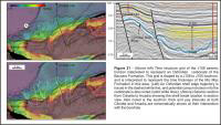
 Canyon system A is eroding a Late Jurassic (Oxfordian?) carbonate ramp system (Figure 21). A structure map showing the erosional character of this surface is shown in figure 21 with the axis of the numerous canyons appearing in white. This scarped edge with clear canyon erosion can be mapped beyond the study area to the east and west. The structure map is draped by an isochron of the overlying J158 to J150 interval which represents the total thickness of the Mic Mac Formation. The isochron shows a dramatic thickening of the Mic Mac Formation basinward of the underlying canyon system. Biostratigraphic data from the Arcadia J-16 well indicate these sediments were deposited in a marine or marginal marine environment (Van Helden, 2004).
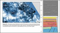
 Canyon system B is an Early Cretaceous canyon system that has been identified in multiple locations eroding sand prone deltaic deposits of the lower Missisauga Formation (the K139 seismic horizon) (Figure 22). The flattened grayscale amplitude slice shown in figure 22 is eroded by this canyon system and in the eastern portion of the study area it erodes much farther landward then other canyons of equivalent age. The trajectory of this canyon suggests it may be supplying sediments to slope areas southeast of this study area.
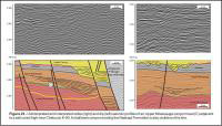
 Canyon system C is another Early Cretaceous canyon but it erodes deltaic sediments of the Upper Missisauga Formation (Figure 23). Canyons of this system erode the K130 marker and in some cases cut as deep as the Lower Missisauga, the K135 and K139 seismic horizons. This canyon has prograding units (bold black lines above dashed line) of Upper Missisauga sediments filling the eroded canyon head and potentially transporting coarser grained material from the Upper Missisauga into deeper waters.
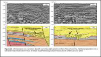
 Canyon system D is one of the better imaged systems within this study because of its shallow burial depth (Figure 24). This Late Aptian/Early Albian canyon system erodes the K 113 seismic horizon and in strike view removes at least 250 ms (twt) of Aptian sediments in its upper section. There are clearly imaged sand prone Cree member units prograding into this canyon system. These prograding Albian sands are interpreted to be equivalent to the gas charged reservoir intervals in the nearby Chebucto K-90 gas discovery.
 These four canyon incisions provide good examples of the interpreted shelf edge erosional systems within the study area. Other equivalent aged canyon systems have also been identified in other areas of the Scotian Shelf. An image of the projected shelf trajectories and canyon systems across most of the central Scotian Shelf is shown in figures 3 and 17.
Shelf to Slope Linked Systems
 Multiple regional seismic horizons are mapped across the 3D surveys throughout the shelf and deepwater (see stratigraphic column in figure 19). On the shelf, these regional markers were used as either flattening datums for producing flattened seismic volumes or used as a datum to extract windowed amplitude information. In deeper waters these horizons were used to create isochrons to locate anomalous thicks that are time equivalent to the periods of canyon erosion on the shelf. The isochrons are limited to an area that has been termed the 'Annapolis Basin' (Figure 20). This deepwater basin is a zone which is constrained to the west by strike-slip faults related to the Balvenie roho system, to the east by a salt weld from a younger salt detachment system of Aptian/Albian sediments and to the south by contact with the allochthonous salt canopy. Within the Annapolis Basin the seismic reflections are continuous and can be confidently correlated. They are also tied to two deep wells, Annapolis G-24 and Crimson F-81. This basin forms a study area for monitoring shifting depocenters throughout the Jurassic and Cretaceous. The isochrons of the four linked systems, presented in the following figures, only displays the shifting depocenters within the ‘Annapolis Basin’.
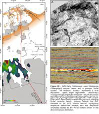
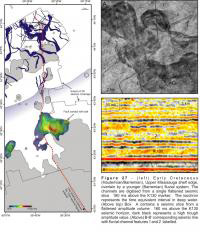
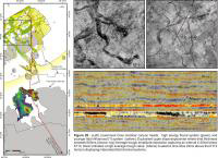
The images shown in this Shelf to Slope Linked Systems section of the study represent four separate time periods: Late Jurassic – Oxfordian/Tithonian, Early Cretaceous - Valanginian, Early Cretaceous- Hauterivian/Barremian and Early Cretaceous – Aptian/Albian (Figures 25, 26, 27, 28). These figures are a compilation of deepwater isochrons, shelf margin canyons and line drawings of seismic amplitude slices from the shelf interpreted to represent paleo-depositional environments.
The Late Jurassic figure combines a Tithonian fluvial system, an older Oxfordian shelf edge (A) and an isochron from the J158 to J150 seismic marker (Figure 25). The isochron represents the time thickness of a Late Jurassic depocenter which is dominantly filled with Mic Mac clastics. There are two possible interpretations of this Mic Mac thick that trends NNE-SSW a) the Mic Mac clastics are filling a paleobathymetric low basinward of an Oxfordian shelf edge and therefore are being deposited in a marine/marginal marine environment or b) this is an area of subsidence due to salt withdrawal. The most likely interpretation is a combination of the two; the interpretation of a marine environment is supported by biostratigraphic data from the Arcadia well (Van Helden, 2004). Jurassic sediments are also deposited basinward of this isochron, however a lack of Jurassic well control prevents the construction of a confident isochron map. The channel systems updip of the isochron were traced over eight time slices 4 ms apart. One slice taken 72 ms above the J150 seismic horizon is shown in inset box A where channels 1-4 are labelled. Channels 1 and 2 are separate fluvial systems with very minor amounts of sinuosity. Channels 3 and 4 are incisions within a broader system that corresponds to gas sand/zone 3 of the Citnalta I-59 significant discovery (CNSOPB, 2000). The accompanying flattened seismic line labels the channels in section view that appear as strong negative amplitude anomalies.
The Early Cretaceous (Valanginian) figure is a compilation of Valanginian Canyon heads (B), an isochron from the J150-K131 seismic marker and Valanginian fluvial systems of the shelf (Figure 26). The orange line drawings on the shelf were interpreted from one average trough amplitude extraction that is 192-236 ms below the K130 seismic marker. Inset box A is an example of the amplitude extraction and the geomorphological detail it provides. Of note in the inset box is the meandering system, on the left hand portion of the image, and also a large (up to ~6 km wide) braided river in the upper right hand corner of the image. Within this braided system it is possible to identify some of the internal architecture and bars and islands of varying sizes appear to be present. This braided system closely corresponds to one of the canyon heads and erodes far back onto the paleoshelf. Although this fluvial system is slightly younger than the canyon head it likely supplied sediments that were transported basinward through the canyon and into deep water southeast of the figure’s extents. Within this figure there is a slight discrepancy between the identified canyons and the deep water isochron. The depositional thick is situated west of all the identified canyon incisions, this implies that this thick deposit was sourced from other canyon systems. The isochron shown represents an interval below the TD of the Annapolis and Crimson wells, suggesting that if the wells had been deepened they would have encountered thick deposits of the Lower Missisauga Formation.
The Early Cretaceous (Hauterivian/Barremian) figure combines elements of the depositional environment during the Upper Missisauga (Figure 27). Line drawing of the shelfal fluvial systems are shown in dark blue and coincide with shelf margin canyon (C), shown in transparent dark blue with an isochron thick lying directly outboard the interpreted canyon incision. The channels are interpreted to be dominantly fluvial systems with examples of meanders and points bars illustrated by the amplitude slice shown in inset box A. There are some smaller diameter channels as well (~160 m wide) with very low sinuosity and could be interpreted to have been formed in a lower energy tidal environment. Of note within this figure are the two wells targeting the deepwater equivalent of the sandy Missisauga interval on the shelf which penetrate an area where the Hautervian/Barremian isochron is thin. Isochron values less than 500 ms (twt) have been clipped from the grid in deep water to highlight the locations of thicker deposits. It is interpreted that isochron thicks, northeast of the current wells, will contain greater volumes of coarse clastics which should significantly increase the possibility of encountering thick reservoir quality Upper Missisauga sands.
The Early Cretaceous (Aptian/Albian) figure displays two shelf systems (Figure 25). The underlying green system is a meandering, high energy system with well defined scroll bars and bar expansion zones (see Inset box A-top). The overlying and younger yellow system is interpreted to be a tidally influenced system. The channel morphology is drastically different than the systems 30 ms below. The channels are narrow (60-200 m) and show no evidence of channel migration, and only have minor amounts of sinuosity. This drastic change in channel geomorphology across 30 ms of data (~ 75 m) may represent a transgression in the system. The isochron in deepwater is slightly offset to the west from the canyon head. Directly outboard the canyon system at this time is a salt based detachment which is accommodating a large amount of sediment passing though this canyon system. This thickness is not represented on the figure due to a lack of well control within the detachment and complicated correlation of seismic markers.
Conclusions
- Shelf edge canyon incisions and progradational packages are present on the central Scotian margin, they can be used to delineate shelf edge trajectories
- Seismic geomorphology studies of amplitude information from 3D seismic surveys on the shelf can be used to interpret depositional settings and aid in mapping the extent of fluvio-deltaic systems
- Isochron grids generated outboard the Sable Subbasin that are time equivalent to the fluvio-deltaic systems on the shelf show that there are thick deepwater deposits that are not penetrated by wells
- Although Annapolis G-24 and Crimson F-81 did encounter sands, they did not test the thickest deposits of Cretaceous sediments outboard the Sable Subbasin.